What Is Er Diagram In Software Engineering
Di: Samuel
An entity–relationship model (or ER model) describes interrelated things of interest in a specific domain of knowledge. Today, we’ll focus on how to diagram, some examples of popular software architecture patterns, and places to find .
What is an entity relationship model/diagram?
Decision Tree in Software Engineering
Class Diagram
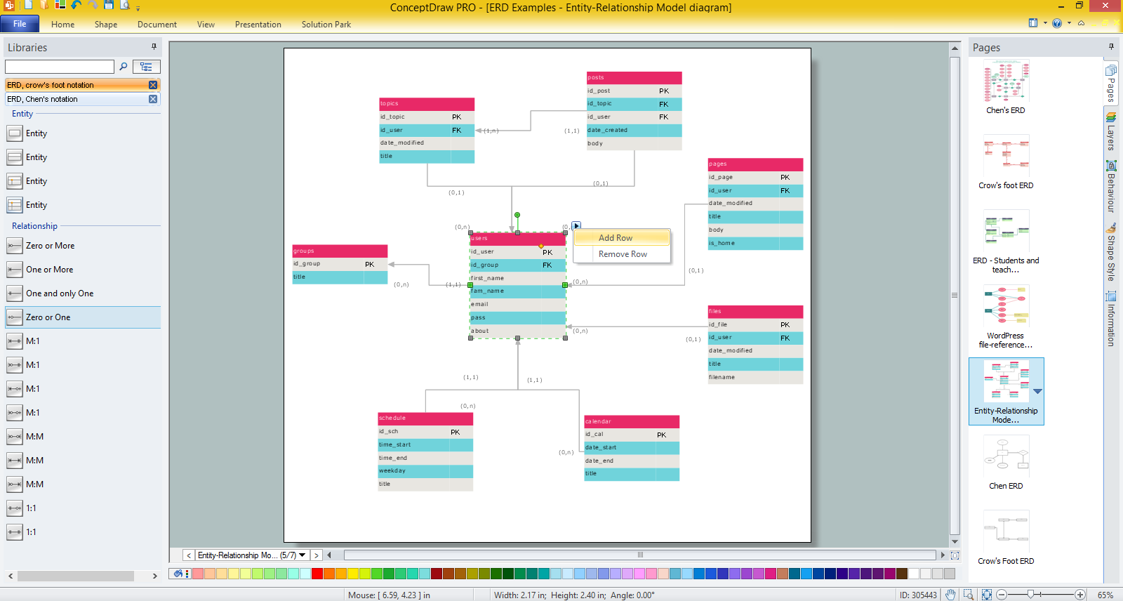
Entity-Relationship Diagramming. Similar shapes are used to identify a particular set of components in an Entity Relationship diagram.Abstract and Figures.
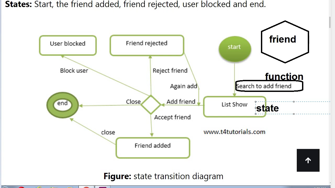
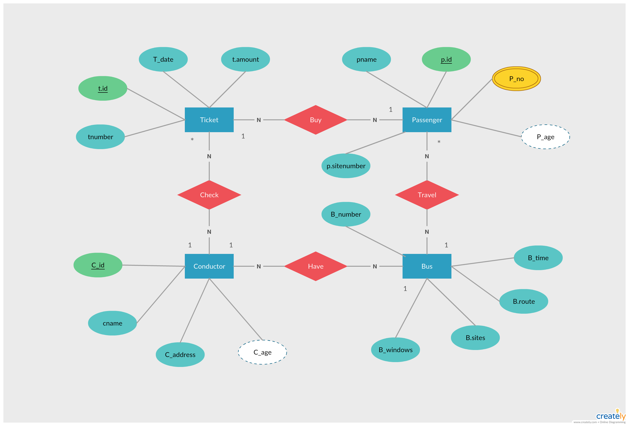
An entity-relationship diagram features category-associated symbols — rectangles, diamond shapes, and ovals, among others, plus lines that connect them (for example, indicating a many-to-many relationship), to illustrate the connections. Here, we will see mainly 3 levels in the data flow diagram, which are: .

What is an Entity Relationship Diagram?
Also known as ERDs or ER models, they .
What Is a Schema Diagram? A Guide with 10 Examples
The system is developed using an ER Diagram(Entity-Relationship Diagram) which represents entities, attributes, and relationships between them thus ensuring a well-defined database schema organized and structured.Explain ER Diagram in Database management system?#dbms #notation #erdiagram Notes: https://csegya.
Entity Relationship Diagram (ER Diagram) Tutorial
vsdx, Gliffy™ and Lucidchart™ files .Entity Relationship Diagram, also known as ERD, ER Diagram or ER model, is a type of structural diagram for use in database design.An entity is a noun, a thing; for instance, a product. These are your use cases. Created by computer scientist Peter Chen in the 1970s, ERDs are commonly .An entity relationship (ER) diagram is a type of flowchart that illustrates how “entities,” such as people, objects, or concepts relate to each other within a system. Class diagrams are used in software engineering to describe the structure of a system.
Flowchart Maker & Online Diagram Software
Add Attributes to Each Entity.
What is ER Diagram: A-to-Z Guide for Beginners!
DeZign for Databases helps teams to visualize database structure. The main aim of UML is to define a standard way to visualize the way a system has been designed. Entity relationship diagrams are used in education to visually represent the relationships between students, teachers, and schools.ER Diagrams are most commonly used in the fields of software engineering, business information systems, education, and research to design or debug relational databases. Use ClickUp Whiteboards and templates to create any type of diagram. In this article will go through the step-by-step process of designing an ER diagram, and defining how entities, attributes, and relationships are defined. Since we can even establish the relationship between numerous real-world entities, it makes ER diagrams extremely .In Software engineering DFD(data flow diagram) can be drawn to represent the system of different levels of abstraction.Start by identifying the “what”s in your system or architecture.They show database capabilities like how tables, keys and columns are used .Class diagrams are a type of UML (Unified Modeling Language) diagram used in software engineering to visually represent the structure and relationships of classes in a system.Entity Relationship Model (ER Modeling) is a graphical approach to database design.
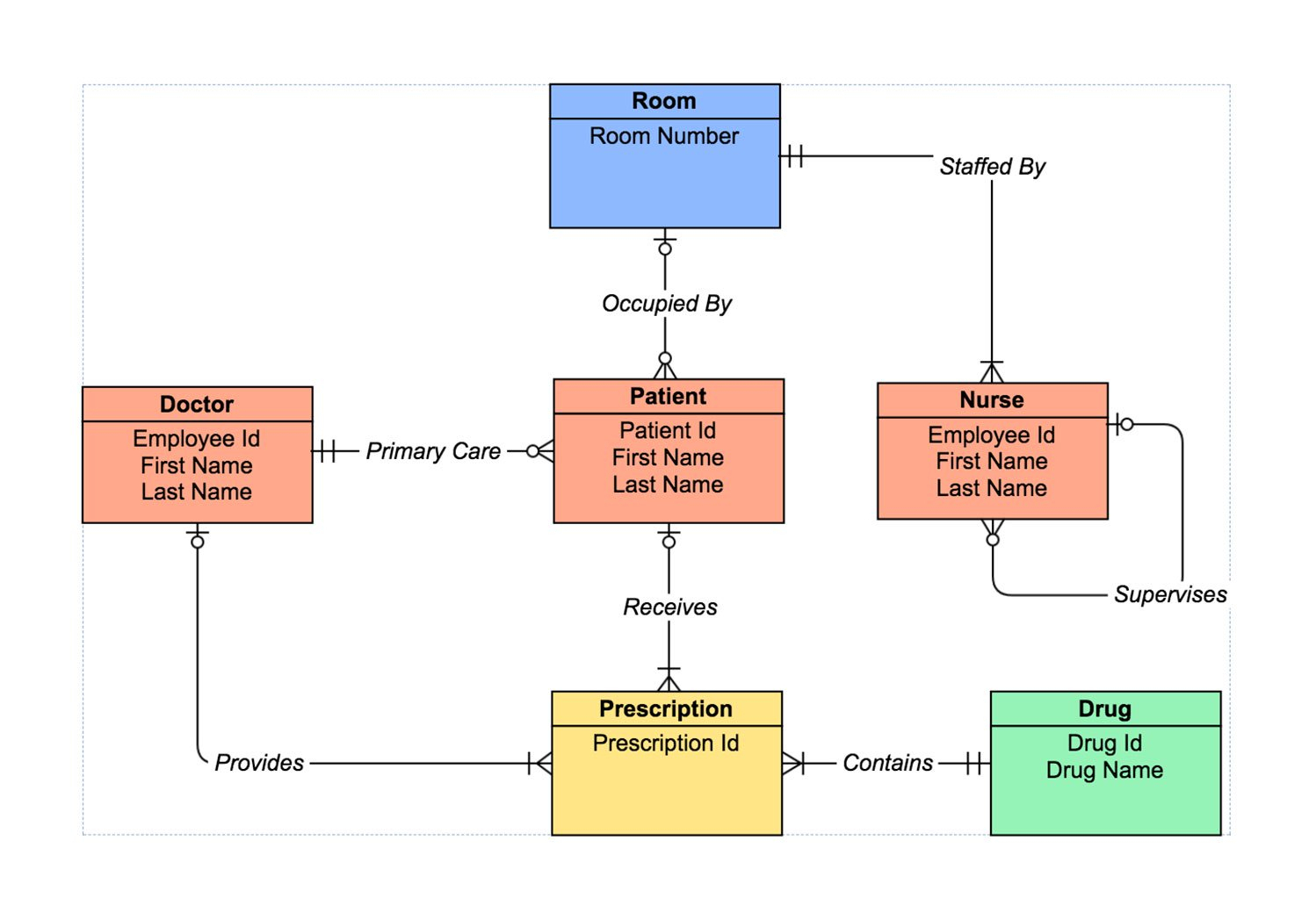
How to Design ER Diagram for a Hospital Management System
They’re most often used to design or debug relational databases used for software engineering, business information systems, education, and research.What is Class Diagram? In software engineering, a class diagram in the Unified Modeling Language (UML) is a type of static structure diagram that describes the structure of a system by showing the system’s classes, their attributes, operations (or methods), and the relationships among objects. You can use it as a flowchart maker, network diagram software, to create UML online, as an ER diagram tool, to design database schema, to build BPMN online, as a circuit diagram maker, and more. An entity-relationship diagram (or ERD) is a visual representation of entities and their relationships in a database. Step 3: Add the attributes of each entity. It also gives insight into the inputs and outputs of each entity and the process itself. Illustrate the various steps involved in a UML use case.Complete playlist for full course of Software Engineering: http://www. DFD does not have control flow and no loops or decision rules are present. DeZign for Databases. SIMPLE : It is simple to draw an ER diagram when we know entities and relationships. With data design platforms like
What Is an ERD in Database Design?
Relationships: UML diagrams are supersets of ER diagrams.Software Engineering Full Course!???https://youtube.Start making your ER Diagram by deciding on all the parts your student management system must have.Enhance your software architecture documentation with diagrams that represent your software’s systems and code for more efficient work, easier understanding, and better collaboration. ER Model in DBMS stands for an Entity-Relationship model. To design an Entity-Relationship Diagram (ER Diagram) for a .In this article, we’ll walk you through the steps of creating an entity-relationship diagram (ERD).in/productsSoftware Engineering . UML is not a programming language, it is rather a visual language. An Entity is a thing or object in real world that is distinguishable from . Next, consider the attributes that you need to describe each entity.
ER Model in Hindi (Entity Relationship in DBMS)
UML Sequence diagrams.
DbSchema is a database design and management system that is based on an ER diagram tool. In those cases, a relationship with its corresponding entities is aggregated into a higher-level entity. Whether you’re a data analyst, a software engineer, or someone looking to visualize the flow of information, understanding these diagrams is essential.
Entity Relationship Diagram Software Engineering
#wingsfortechnical
Decision Tree in Software Engineering. An ERD contains different symbols and connectors that visualize two important information: The major entities within the system scope, and the inter-relationships among these entities. ER diagrams in DBMS are blueprint of a database.Notation of Entity Relationship Diagram (ERD) in DBMS Hindi. Step 3: Connect Actors and Use Cases. When you know how to use an entity relationship diagram, you can make sure that large sets of data are organized, which means ERDs are most often used for software, . You’ll need to leave the area in your design for these rectangles to be included later. There are a lot of diagramming tools out there that are designed specifically for project managers.DFD is the abbreviation for Data Flow Diagram.Hospital Management System Features.!#LearnCoding#DF.
Build Better Applications with Software Engineering Diagrams
Data Flow Diagrams. The software is able to create ERDs for relational and NoSQL databases. Usage: Design and tracking the entire software architecture are done with it.
What is The Entity Relationship Diagram (ERD)
UML Class diagrams. After you’ve decided on the entities, think about the traits you’ll need for each one.LibreOffice – Open Source.com/playlist?list=PLqleLpAMfxGB1g0xlYj2H6lyY2Q2ku7p9Don’t forget to tag our Channel.In ER diagrams, the objects and their relationships are represented graphically. Here are some common uses of activity diagrams: Dynamic modelling of the system or a process.If you are related to database management or software engineering, then you might already be aware of ERD. It stands for Entity Relationship Diagram and lets us create a visual representation of different linked entities together. UML is a standardized modeling language that helps in designing and documenting software systems.
Entity Relationship Diagrams, also called ERDs or ER Models, are a diagram that describes how entities relate to one another within a defined space or system. Higher-level DFDs are partitioned into low levels-hacking more information and functional elements.com OR https://www. ConceptDraw DIAGRAM as a powerful Entity . A basic ER model is composed of entity types . This section will explore how ER diagrams can support requirements gathering and analysis, iterative . Aggregation is an abstraction through which we can represent relationships as higher . Running into issues during a project can cost a lot of valuable time and resources, so it .In the world of database design, entity relationship diagrams serve as valuable tools for designing complex systems and their relationships. Create Class Diagram. During the planning phases of software development, software engineers often use ER Diagrams. ER diagrams are a visual tool which is helpful to represent the ER model. The latter makes it simple to determine which system elements will be involved and how they relate to one another. Model software elements like methods,operations .ER Diagram is a graphical representation of entities and their relationships which helps in understanding data independent of the actual database implementation. In it, database designs and implementations are handled. EFFECTIVE : It is an effective communication tool.An ER diagram is not capable of representing the relationship between an entity and a relationship which may be required in some scenarios.
What is an Entity Relationship Diagram and How Do They Work?
In software engineering, an ER model is . It is mostly used for Java and other DBMS.Entity Relationship Diagram (aka ERD, ER Diagram, E-R Diagram) is a well-tried software engineering tool for data modeling, system design and illustrating the logical structure of databases.Flowchart Maker and Online Diagram Software. ER diagrams are used in software engineering during the early stages of planning projects.universityacademy. An example of this is creating inventory software for a retail outlet. A class diagram uses UML to show the classes, attributes, methods, and their relationships to each other, in the system. You can use DeZign for Databases to create new databases or reverse-engineer existing databases. All entity types, for example, are enclosed in a .In conclusion, ER diagrams and schema diagrams serve as pivotal tools in the world of data management, software engineering, and database design.11 best ER diagram tools to use in 2024. UML Diagramming. The ER model is a high-level data model diagram.software engineeringentity relationship diagram
What is an Entity Diagram (ERD)?
Download Notes of All Subjects from the Website:https://universityacademy. The ER diagram corresponds to the UML diagram.Software architecture diagrams are an important documentation practice that will help you plan for and implement changes in your network, visualize strategic initiatives, and stay ahead of your organization’s needs. They help to identify the different elements and define relationships.Step 2: Identify Use Cases. Entity relationship diagram DBMS displays the relationships of entity set stored in a . Identify the main functionalities or actions the system must perform. The flow of data of a system or a process is represented by DFD.
E-R Diagram in DBMS ( Hindi)
It is quite similar to blueprints used in other fields of engineering. This software also allows you to create organizational charts but not for free.
Use Case Diagrams
Levels in DFD are numbered 0, 1, 2 or beyond.
Unified Modeling Language (UML) Diagrams
Software engineering is a discipline utilizing Unified Modelling Language (UML) diagrams, which are accepted as a standard to depict object-oriented design models. This is one of the best free and open-source alternatives to Microsoft Office. Entities are represented with a rectangle, and you’ll want to give them plenty of room so that you can add to your diagram in the next steps. We use UML diagrams to .Create ER diagram. They are an integral part of the software development .
A basic ER model is composed of entity types (which classify the things of interest) and specifies relationships that can exist between entities (instances of those entity types). The perimeters of a choice tree represent conditions and therefore the leaf nodes represent the actions to be performed looking at the result of .A data dictionary in Software Engineering means a file or a set of files that includes a database’s metadata (hold records about other objects in the database), like data ownership, relationships of the data to another object, and some other data.ER diagrams are a visual tool used to represent and analyze data structures.An entity relationship diagram (also known as an ER diagram or ERD diagram or simply ERD) shows how entities (people, objects, and concepts) interact. An ER model is used to represent real-world objects. The entity, ‘Products’, .ly/ipsoftwareengineeringTopics covered (in Hindi) :• ER Diagrams for Software Engin. Specific operations depending on the type of data can be .Activity diagrams are used in software development and system design to model and visualize the dynamic aspects of a system.
A Decision Tree offers a graphic read of the processing logic concerned in a higher cognitive process and therefore the corresponding actions are taken. EASY TO UNDERSTAND : The design of ER is very logical and hence they are easy to design and understand. Let us understand the terminology of ER Modelling through the following docket. In the context of agile software development, ER diagrams can be particularly useful for understanding and documenting the data that is needed for a project. Professional ERD drawing is an essential software engineering method for database modeling.ER Diagram घटक वर्णन; एंटिटी (Entity: एक इकाई (entity) डेटा का एक वस्तु या घटक है। सरल शब्द, यह एक वस्तु, व्यक्ति, स्थान आदि हो सकती है जो डेटाबेस में डेटा संग्रहीत करती है . It is a high-level data model that defines data elements and their relationship for a specified software system. DeZign for Databases works well for many teams.Unified Modeling Language (UML) is a general-purpose modeling language. These conceptual data models help developers and designers visualize the relationships between key software elements. The diagram editor provides a library of ERD symbols and the designer places them on the canvas to create an entity and add attributes to it. Example a data dictionary entry: GrossPay = regular pay + overtime pay. Draw lines (associations) between actors and the use cases they are involved in. If you are looking for programs to create remarkable free charts and ER diagrams, you should consider trying LibreOffice. Each use case should represent a specific piece of functionality. ERDs can also be . We’ll explain when you need to use an ERD and what notations and tools are used to build ER diagrams. Entity relationship diagrams are extremely .io can import . A sequence diagram .ER Diagrams are often used to design or debug relational databases in software engineering, business information systems, education and research.io is free online diagram software. An ER diagram tool also often shows attributes for .Software Engineering.Now that you know which features will make diagramming go more smoothly, check out these 10 tools that offer the essentials and beyond.
- What Is An Inspirational Speech?
- What Is My Miranda Kerr Home Collection?
- What Is Eva Mendes Net Worth? _ Eva Mendes Bio, Age, Height, Husband, Kids, Movies, Wiki & Net Worth
- What Is Isd Code In Spain? _ How To Recycle In Spain
- What Is Entropy In Psychology?
- What Is Made From Crude Oil | What products are made from petroleum?
- What Is Assault _ Assault
- What Is Germany Phone Code 49?
- What Is Cloudnine Care At Home?
- What Is Costco Membership? – Is a Costco Membership Really Worth It?
- What Is Multiple-Dose Activated Charcoal (Mdac)?