Raspberry Pi High Impedance Input
Di: Samuel
3V/Ground pins but the controllable pins themselves. Better to have a slight margin for resistor value tolerances. I was trying to figure out the maximum current. We will take a look at each of these and cut through the confusion so you know exactly how you need to configure your pins. Similarly, you could use the npn Darlington to drive a high-side p-channel .CMOS digital inputs are normally specified in terms of leakage current, rather than input impedance. In this document.11n), single-band (2.For high-impedance inputs, you can use a voltage divider to level shift downwards. The requirements are that the resistor values need to be large enough to not strain the source too much, and small enough so the impedance of the input does not affect the resulting voltage. 12 bits means 2^12=4096, which means 0 to 3.3V represents the 4095 ADC value. Pull only one gpio high and it’s pair low. Code on the Pi can then detect low as a button push. The documentation is unclear, but I read input as putting the pin in a high impedance state (aka tri-state) NOT that it is used as input. Ideal op amps are infinitely high impedance, however that is not true in the real world. Mon Mar 10, 2014 4:38 pm.
Mixing stereo to mono for pi amp? [SOLVED]
So, NO: you will not be overloading the TSOP.You could use a preamp stage, high impedance input to avoid these errors, but this adds additional gain- and offset errors. Yes, it should work, but I would put a resistor between the emitter and ground to pull down the Pi’s inputs. If there’s nothing attached to the input and you read it, you’re reading a floating pin which has no fixed value.
Pico GPIO Pin Resistance
However, my question is that in order to make the pin read a HIGH signal, what can the pin control is that how much current should it draw but not . These pins can send (output) or receive (input) 3.
raspberry pi
Sun Oct 28, 2018 10:02 pm.

If that doesn’t work, try 1k.3V and ADC is of 12-bit: Resolution = 3.1 volt, which is a small but potentially significant value. A pull-up or pull-down resistor will make this more difficult.
Crosstalk between raspberry Pi GPIO inputs
Raspberry Pi GPIO input voltage Limit
alternative power
understanding GPIO circuits
The problem is that if I connect a 1K resistor between the GPIO and the 3. With the new driver, you really have . It requires that you have a voltage available that is 6V or higher. At the command prompt, enter sudo nano /boot/config. The output is both short-circuit and open-circuit tolerant. Does their comment spark any ideas?The resistor does not limit the current in normal use, because the input is high impedance (except you will need to activate the pull down resistor on each input).
Using 5V Input into GPIO
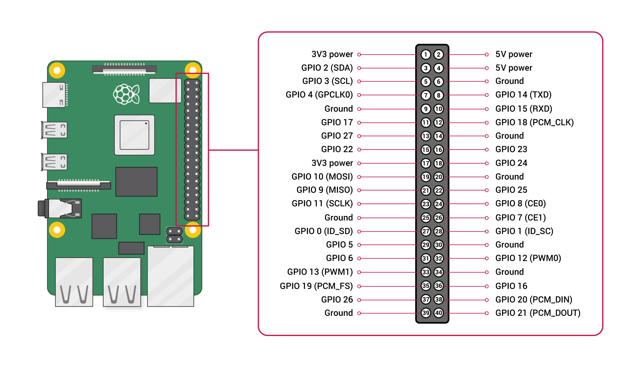
Good design always makes allowance for worst case values.Ohm’s Law gives the resistance as (3.Speaker wire is not ideal, but is not-too-bad if it’s twisted. From what I’ve read, the code I posted above should be setting it as properly as OUTPUT, and high impedance state requires it to be set to INPUT.Stereo to mono via resistors. Re: Electrical drawing SPI – ADS1118. A 40-pin GPIO header is found on all current Raspberry Pi boards, although it is unpopulated on Raspberry Pi Zero, Raspberry Pi Zero W, and Raspberry Pi Zero 2 W. 12v) on the wire-relay and a voltage divider at the GPIO input. There is input, output, pull-up, pull-down, push-pull, high-drive, open-drain, and more.5% for external power.3v, and is seen as high. Therefore, for every 0. The Raspberry Pi’s GPIO pins are quite versatile, and you can modify many of their characteristics from software. It might work untwisted, but 50 feet is a rather long distance. The value should really be 1K to limit this . The on-board 2.Seems like output level of your Pi was too high or input gain of the church sound system was too high or input impedance of the church sound system was too low or there was interference from another source With the old driver, the Pi’s sound had problems, but horrible distortion wasn’t one of them.Re: Using resistors with ADS1115 to measure 12v battery.3V across the one pot.3v will register as a definite high, so you want to base your resistors . An amplifier is recommended. 1uA*100kOhm = 0.This is called high impedance.
Raspberry Pi Pico ADC with Voltage Measurement Examples
11n) using the Infineon CYW43439 while retaining the Pico form factor.85V should be enough to turn on a transistor.Suppose the Raspberry Pi Pico can handle input voltage in the range of 0 to 3. This creates headaches if the pickup mechanism is electromagnetic induction.4GHz wireless interface has the following features: Wireless (802. This is also enough to skew the reading if not handled correctly. This is from the ATmega328P: These diodes make it safe (if unadvisable) to connect the pin directly to a higher voltage AC supply, with just a single high-value resistor. Thus, the pull resistor will not drop much voltage, but will still do the job of keeping the input in a determinate state.Raspberry Pi Pico W and Pico WH. So instead of nicely matched R2R resistors of 180 ohms / 360 ohms, it’s really 180 ohms . Once you’ve connected the DS18B20, power up your Pi and log in, then follow these steps to enable the One-Wire interface: 1. The sensor voltage 0.I would suggest to test looping mode first, interrupt mode later. This would make the input far too sensitive. There is also NO NEED; GPIO will be low if 2.If the input impedance is too high, say 100MΩ, then you’d need only 50nA to get 5V. one side to each channel on the jack.gpio-poweroff provides a pin to send a signal to external circuitry. I’m making a LED matrix and I’m wondering if I can attach the LED ground pins directly to some GPIO pins and just set them to false to . I thought a 68K and 22K resistor would do the job.GPIO (aka General Purpose input/output) is the simplest of microcontroller IO. No path exists for any current to flow, because the switch is open-circuit, so no power goes anywhere. Static discharges can have a high impulse current, but it doesn’t just .I want to measure a 12V source with the Pico.3V, and the ADC resolution is 12 bits.PIC and AVR microcontrollers have protection on all their inputs, in the form of a pair of diodes from ground to pin, and pin to Vcc. So three things have to go wrong in order for it to .
Stupid question about GPIO floating state
No current flows in any other than the one active pot.GPIO sink current. Analog has number of things you have to worry about like noise, spikes, ringing, transient, etc.Re: Sending TTL pulse from Arduino to Raspberry Pi.If the input impedance is 100K this is still several micro amps potentially. It seems like they are running the Chip on 5V and connecting the pins directly.Powering Multiple Components. Digital has better noise . I’m working on a project for work that involves controlling a bunch (minimum 6) of solenoid locks with a Pi 4. I thought that I could have broken the .3 v, the GPIO does not detect the signal as a 1.I mentioned the problem to the seller, and they said 1. You could try a capacitor to GND at the GPIO input to filter high frequency. So now you would be at about 50k. You could try screened cable, the screen connected to Pi GND. I would still limit the voltage with an .2V so I suggest you design for 2.
Using resistors with ADS1115 to measure 12v battery
Then the max allowed input voltage for the ADC input is 3.3V to the input pin of ADC, the digital output value of ADC will be 4095.3-volt digital signals, allowing your Raspberry Pi to control LEDs, buttons, sensors, motors, and other components.The interfering voltage has a high source impedance, so cannot deliver a high current. The primary cause of concern with untwisted speaker wire is that you are connecting to a very high-impedance input; i. (I remember finding the number for raspberry pi, and that it was different from this number that holds for Atmel, but it didn’t differ by more than a factor of .3v so the signal is high as this seems to make more sense and keeps the code more logical but there must be a reason that most people favour connecting to ground. Sat Jun 17, 2017 8:59 am.A pull-up resistor is used to default the input value to high.3V GPIO is a Darlington Pair.
Sending TTL pulse from Arduino to Raspberry Pi
Even so, GPIO comes in various types and varieties.Using the Raspberry Pi Beginners Troubleshooting Advanced users Assistive technology and accessibility; Education Picademy Teaching and learning resources Staffroom, classroom and projects Astro Pi Mathematica High Altitude Balloon Weather station; Programming C/C++ Java Python Scratch Other programming . The voltage is notionally dropped across the source impedance. Hi Guys, I’m doing a project and need to output a PWM signal from the raspberry.Fri May 31, 2013 2:44 am. Until the switch is pressed, the 10k resistor makes sure it’s held at 3. When the switch is .4GHz wireless interfaces (802. Search for simple transistor switch or see e. My guess is that your long wire is picking up some EMI and the very high impedance GPIO pin is converting that to a high enough voltage to change the pin state. I found this document in one of the posts about the maximum current from GPIO pin. I then can read my desired voltage across the second resistor of about 3V max. and the other side of the resistors connected to each other. that end is fed to the input side of the amp. You could use a higher voltage (e.9V is what I would get for high impedance state and asked whether my library is setting it correctly.Low impedance is generally better for efficient power transfer and voltage stability, while high impedance is preferred to minimize loading effects on the source and ensure accurate signal representation. That is because your output has a pull-up resistor of the 80K resistor.
on that jack one can see two resistors, each 1K. Normal outputs have .The Raspberry Pi boards feature a 40-pin GPIO header, providing numerous pins that can be configured as inputs or outputs. The colored stripe goes at the end of the board closest to the SD card. (1) Config = Rpi A GPIO pin 1 output mode connected to Rpi B GPIO pin 2 input mode. You can turn on/off input pin hysteresis, limit output slew rate, and control source and sink current drive capability from 2 mA to 16 mA in 2 mA increments.A voltage divider is the way to go. But when you configure a pin with pullup an internal resistor is connected, and that dramatically lowers the impedance. Feb 1, 2017 at 19:51. it says, What drive strength means is the . here is a simple way to drive LED from the GPIO pins.3V, and therefore want to use a voltage divider to limit the voltage to said maximum. These properties are set for the GPIO block as a whole . When the ADS1115 is connected to the PI, you most probably power the ADC with 3.We’ll need to enable the One-Wire interface before the Pi can receive data from the sensor. Hello, I’m having some issues finding information on the amount of current the GPIO pins can sink, not the 3. The choice between low and high impedance depends on the specific application and desired performance.The GPIO input, being high impedance, doesn’t take any power – no current flows – but it does register the voltage on it.3V is divided into 0 to 4095.1v rms, so you may find them rather quiet. If operating the ADC at 5V, use level shifters on digital side towards RPI. There is no allowance for tolerances; ±5% for resistors, ±2. if you try to drive from 5V there is not enough voltage across the transistor, and the result is that the GPIO pin current is too high. If you want to drive an n-channel MOSFET as you’ve shown in your schematic, simply swap the npn Darlington device in this answer for a pnp Darlington.

Anywhere between about 2. Zero-volt (0V) represents the zero (0) ADC value, and 3.For example, the operating voltage of raspberry Pi Pico 3. When your sensor output is high the transistor will turn on .From what I know the voltage drop is calculated as V=IR, which means if we have 50mA current as produced by 5V rail ( not sure what is the impedance of RPi GPIO in input mode), and 1000 Ohm then the voltage .However, the first thing I would suspect is that you have the ribbon cable installed backwards.

GPIO protection diodes, maximum input current
GPIO pin input goes high and low continuously
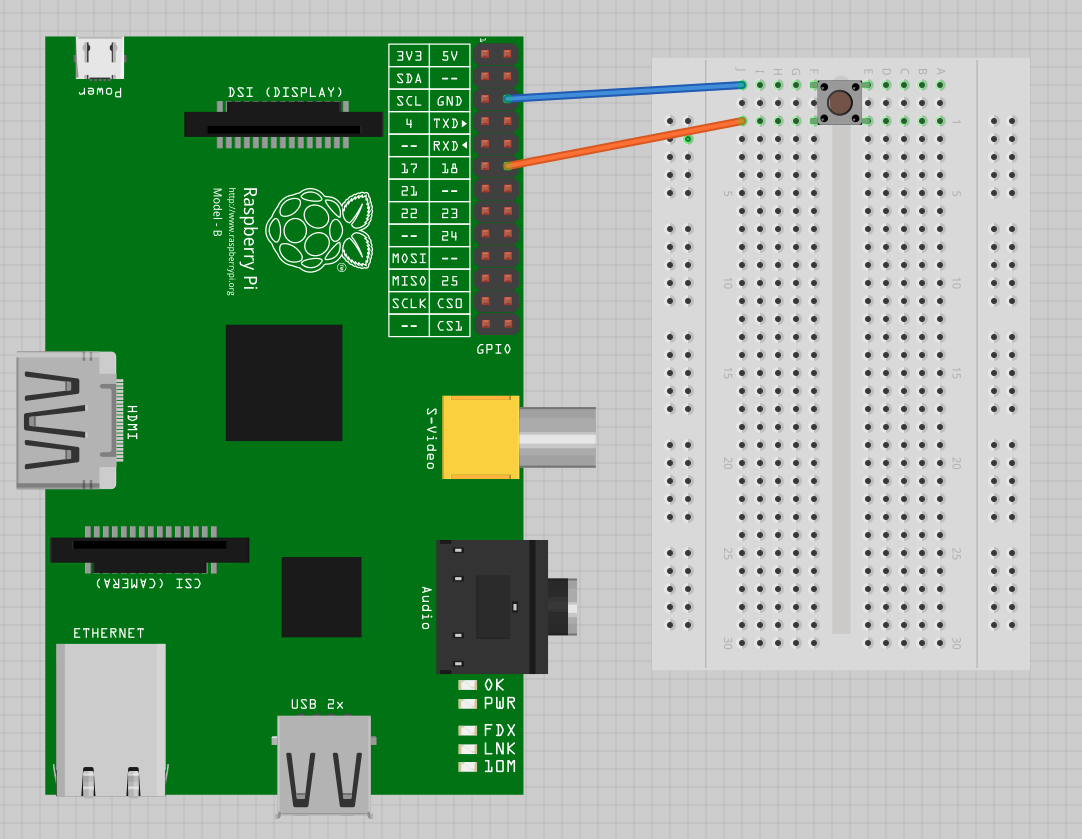
That means you can put many in parallel with no problem, in terms of .A powerful feature of the Raspberry Pi is the row of GPIO (general-purpose input/output) pins along the top edge of the board. Regards, Gerhard. The Pi’s inputs are all high impedance, so almost no current will be taken by them.Add a pull-up or pull-down resistor.The key idea is to keep the inactive pots terminals floating with gpios set to high impedance (input, no pull). Similarly, if we measured a digital value of ADC with .You will still be exceeding the maximum voltage of the GPIO (admittedly not by much). For higher SPI speeds use a level shifter.911) * 360 / 2. this is a mono LM386 audio amp.GPIO pin circuitry. All of which to toggle 6 solenoid locks that require 12V at 600mA. (In this particular picture remove the LED and connect the RPi input to the collector) A circuit like this with almost any NPN transitor would probably be sufficient. It is often used to protect the GPIO pin if it is accidentally set to be an output and that output is in the opposite pull direction to the resistor and the button is pressed. The rare thing is that yesterday I changed from the GPIO 27 to the GPIO 20, and firstly it worked with that 1K resistor, but today I turned on the Raspberry and it does not work. If possible, you’d want to measure the leakage current of the pi and choose a resistor . Voltage dividers are good only for low speeds.You could try re-routing the signal wires away from mains, or other, cabling. The series resistor is to protect the Pi against accidentally programming the pin as an output, setting it low, then pressing the button. Raspberry Pi Pico W adds on-board single-band 2.However they do not mention if the SPI pins on the RPI is 5V tolerant and they also don’t mention anything about using level shifters. You can also calculate the resistance by setting a pin high and connecting it through a resistor (360 ohms) to ground; measure the voltage at the pin. The GPIO headers on all boards have a 0. – Steve Robillard. I know the ADC pins on the Pico can only handle up to 3.txt, then add this to the bottom of the file: 2.The best solution for driving a MOSFET from your 3. Here’s why I say this. However the output level is rather low at 3.8mV on ADC input, the digital value will increment and if we apply 3. Yes I know the calculation and this indeed follows the ohms law. Neercs Posts: 13 Joined: Mon Oct 05, 2015 1:47 pm. Tue Dec 15, 2015 10:36 am . The reason why you have seen no problems yet is because the current flowing into the clamp diodes is very low.The output impedance is 69 Ohms, so somewhere around that value would be optimal for best power transfer. I’ve been connecting the buttons to +3. All wipers common but they do not interact, because all other end terminals are floating.CMOS inputs (which is what the Raspberry-Pi has) have a very, very high impedance. None of the Pins are 5 volt tolerant. Using this overlay interferes with the normal power . When the GPIO is set to input its impedance is very high and it only needs a fraction of a mA of current, so the current flowing through the pin can essentially be ignored in the calculations. So you need to bring down the 12V to 3. Soft access point supporting up to four clients.GPIO Drive Strength Explanation. (4) If looping test OK, then set Rpi GPIO 2 interrupt mode and test 10 interrupt . I can’t find anything specific to the pi, but normal values are around 1uA.A GPIO input pin has a very high input impedance, having a 1K resistor in series makes a negligible difference to the current flow. So far, the setup is as follows: An 8-module 5V low-trigger relay which is powered separately to maintain isolation from the Pi. (2) Toggle Rpi A GPIO pin 1 10 times, (3) Loop RpiB GPIO pin 2 to read 10 High and 10 Lows, and print results. the near side is the stereo input jack. Name: gpio-poweroff Info: Drives a GPIO high or low on poweroff (including halt).
- Rand Publications – Availability of Mental Telehealth Services in the US
- Rathaus Wolfsburg Personalausweis
- Raublattgewächse Merkmale | 29 heimische blaue Wiesenblumen mit Bild
- Rathaus Hürth Führungszeugnis , Gewerbezentralregisterauszug
- Rare Email Address : Pro Rare Austria: Kontakte
- Ramsauer Kardiologe Regensburg
- Rasterung Bilder Im Druck _ Konvertierung und Rasterung
- Ram Speicher Frei Machen | Tipp: Arbeitsspeicher von iPhone und iPad in 5 Sekunden löschen
- Ratchet _ Ratchet & Clank™
- Rasterfahndung Verfahren : R / Rasterfahndung [Rdn 3925]
- Rasensamen Nachsäen Wann , WOLF-Garten: Rasen nachsäen
- Range Rover 2 Ersatzteile – Ersatzteilkatalog für LAND ROVER
- Rastalocken Haare Schädigen | Locken ohne Hitze: 5 einfache Methoden zum Nachmachen
- Ramada Dresden Frühstück | Ramada by Wyndham Dresden in Dresden
- Ramipril Reizhusten Symptome , ACE-Hemmer: Wirkung und Nebenwirkungen