Phasor Circuit : Circuit Theory/Phasor Analysis
Di: Samuel
This Demonstration shows a phasor diagram in an AC series RLC circuit The circuit consists of a resistor with resistance an inductor with inductance and a capacitor with capacitance The current in an RLC series circuit is determined by the differential equationwhere and is the AC emf driving the circuit The angular frequency is related to .In this video, phasor, and Phasor Diagram for AC circuits have been explained. The input is a sinusoidal current, I s (t) at 6. In the time domain, to find the output, we would need to convolute the input with the impulse response. In studying the behavior of electric and magnetic circuits, we encounter three types of . Electrical Quantities of RL Series Circuit. A phasor diagram consists of vectors that represent the amplitude and .Where is the phasor representation of the circuit’s output, and is the representation of the circuit’s input.Because the radian frequency ω remains the same in a linear circuit, a phasor just needs the amplitude VA and the phase ϕ to get into polar form: V = VAejϕ. The converter in the rotary time frame, as shown in Fig. Events such as various types of faults, tap changes, switching events, circuit protection devices.
Equivalent Circuit And Phasor Diagram Of Single Phase Transformer
Open the example named Transient Analysis of a Linear Circuit (power_transient).
Phasor Diagram and Phasor Algebra used in AC Circuits
Simplify an entire RLC network into a simple series or parallel equivalent comprised of complex impedances. Impedance Calculation in RL Series Circuit Example 1. Phasor analysis is a useful tool for simplifying three phase waveform generation and distribution by representing voltage and current quantities in graphical form. By representing voltage and current as phasors, we can easily determine their magnitudes, phase angles, and the power factor of the circuit. Recall that current and voltage are in phase for purely resistive AC circuits, while current leads voltage by 90 degrees in purely capacitive circuits.Electrical, RF and Electronics Calculators. Letter Symbols for Phasor Quantities. The phasor diagram also helps us understand the concept of impedance, which is a measure of the .In this video, we demonstrate how to find the absolute phasors across various circuit elements by running an AC Single Frequency Analysis in NI Multisim.The system order is drastically degenerated from .4 Lecture 16, 10/07/05 EE40 Fall 2005 Prof.Autor: Mahesh Shenoy
Phasor Diagram Creator
1 Application of the Unified General Phasor Transformation to AC Converters. Next, we solve the phasor circuit in Fig.Three windings transformer per unit impedance the engineering knowledge single phase equivalent circuit an overview sciencedirect topics guide to power transformers theory phasor diagram and of a lessons blende ex 404 electrical machine i potential 8 important asked in exams what is quora ppt topic 1 magnetic concept . And we are interested in finding the B/A division of the phasor, the resultant stationery vector will be. Phasor diagrams are used in simple harmonic motion . learning objectives.Ece 2120 electrical engineering laboratory ii polyphase ac power basic alternating cur theory automation textbook 2 review of circuit and application phasor diagrams circuits systems in practice book using geogebra to enhance student understanding courses rc analysis series parallel explained plain english electrical4u .
RC Series Circuit
Before discussing the use of complex numbers to solve circuits with time-varying voltages and . The phasor diagram is based on the complex plane discussed previously where the horizontal is the real axis and the vertical is the imaginary ( j j) axis.2b, by the power-invariant phasor transformation [].
Phasor-Domain Circuit Analysis
A powerful tool used for understanding the operation of AC circuits is the phasor diagram, consisting of arrows pointing in different directions: the length of each arrow representing the amplitude of some AC quantity (voltage, current, or impedance), and the angle of each arrow representing the shift in phase relative to the other arrows. Figure 1 shows the construction of one phase of the armature winding. Graph functions, plot points, visualize algebraic equations, add sliders, animate graphs, and more. 1: A time domain plot.A phasor can also be expressed in rectangular form, i. Determine the voltages across and the currents through the circuit elements when the generator is connected to (a) a 100 − Ω 100 – Ω resistor, (b) a 10 − μF 10 – μ F capacitor, and (c) a 15-mH inductor. Yagle, EECS 206 Instructor, Fall 2005 Dept.This beginners-level introduction to phasors concludes with a derivation of the average power for an ac circuit element when there is a phase shift between the current and voltage.They can also be used to show how various voltages or currents combine. The following steps are used to draw the phasor diagram of RC Series circuit. For example: Thus, the polar-form phasor 5 ∠ 36.
Parallel RC Circuit
Phasor Analysis of Transformer Circuits. NeureutherLecture 16, Slide 2 .
Phasor Diagram for Series RLC Circuits
All currents/voltages are replaced by their phasors, and all circuit elements are replaced by their impedances. A series RLC circuit contains elements of resistance, inductance, and capacitance connected in series with an AC source, as shown in Figure 1.Continuous Phasor Simulation of a Circuit Transient. For circuits without a resistor, take R = 0; for those without an inductor, take XL = 0; and for those without a capacitor, take XC = 0. We can see from the phasor diagram on the right hand side above that the current vectors produce a rectangular triangle, comprising of hypotenuse I S, horizontal axis I R and vertical axis I L – I C Hopefully you will notice then, that this forms a Current Triangle. The phasor diagram of Figure 4 is much easier to draw than the instantaneous voltage graphs of Figure 2, and it shows the RMS values and phase angles at a glance.
Complex Numbers, Phasors And Phase Shift
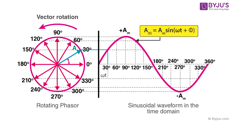
Phasors are rotating vectors having the length equal to the peak value of oscillations, and the angular speed equal to the angular frequency of the oscillati. This guide covers Parallel RL Circuit Analysis, Phasor Diagram, Impedance & Power Triangle, and several solved examples along with the review questions answers. By representing each .Figure (2): RC Series Circuit Phasor Diagram. For a more sophisticated example of phasor algebra that uses calculus to understand the momentum of electromagnetic radiation, visit: Explain why the voltage across an inductor “leads” the current in an AC circuit with an . When a voltage is applied to the coil, current flows in the winding and flux is established, just as in the transformer. Problem: An AC series RL circuit is made up of a resistor that has a resistance value of 150 Ω and an inductor that has an inductive reactance value of 100 Ω.This guide covers The combination of a resistor and capacitor connected in parallel to an AC source, as illustrated in Figure 1, is called a parallel RC circuit. After the switch is closed, find the time constant, maximum charge on the capacitor, the charge on the capacitor after 6s after switch is closed. Compute complex equivalent impedance for series-parallel RLC circuits. They provide a way to simplify complex AC circuit calculations and understand the relationships between voltage, current, and impedance.Solved Examples.
相量
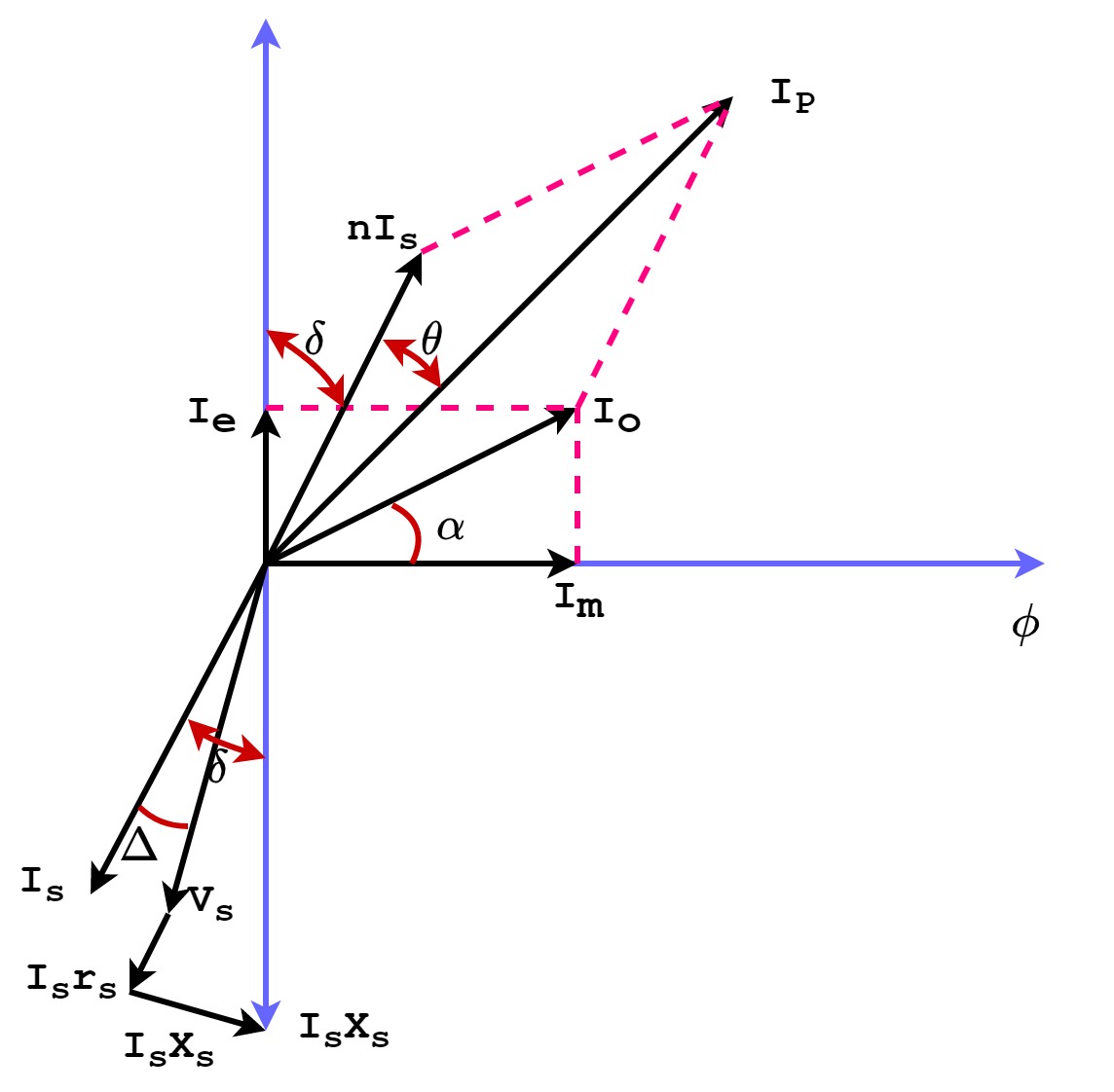
Professor Andrew E.COMPLEX NUMBERS AND PHASORS.1 Rectangular Versus Polar Form. Phasor diagram of synchronous motor. where I a R a is the voltage drop per phase in the armature resistance and I a X S is the reactive voltage drop per phase due to armature reactance and armature reaction effect. Inductors in AC Circuits: Inductive Reactive and Phasor Diagrams. Designer’s Guide Consulting, Inc. The voltage drop V R will be in phase with current I and voltage drop V C will lagging current I by 90º. To understand why phasors are useful, consider the circuit shown which shows a current source driving a series combination of a resistor and inductor. The value of impedance is calculated by using the Pythagorean theorem ( equation 7–15 ). Phasor algebra is used in AC circuit analysis for addition, multiplication, subtraction, and division. The phasor diagram is drawn taking current ‘I’ as the reference. Figure 1 Series RLC circuit diagram.Phasors: Impedance and Circuit Anlysis OUTLINE • Phasor Re-Cap • Capacitor/Inductor Example • Arithmetic with Complex Numbers • Complex Impedance • Circuit Analysis with Complex Impedance • Phasor Equivalent Circuits Reading Hambley 5. An ac generator produces an emf of amplitude 10 V at a frequency f = 60Hz.
Phasor and The Phasor Diagram in AC Circuits Explained
First, we convert the circuit to the phasor/impedance form as shown in Fig.1 Review of Complex Numbers 7.相量(英語: phasor )是振幅(A)、相位(θ)和頻率(ω)均為非時變的正弦波的一個複數,是更一般的概念解析表示法的一個特例。 而將正弦訊號用複數表示後進行電路分析的方法稱為相量法,而在相量圖中利用向量表示正弦交流電的圖解法稱為向量圖法。相量法可以將這幾個參數的相互依賴性 .Simple AC Circuits.This guide covers Series RC Circuit Analysis, its Phasor Diagram, Power & Impedance Triangle, and several solved examples.Therefore, when resistance and capacitance are combined, the overall . Machine learning and signal classification methods can be used to develop algorithms to identify these significant events.

Abstract The purpose of this document is to introduce EECS 206 students to the concept of phasors–complex numbers used to represent sinusoids, to simplify the math of .
Understanding Phasor Diagrams in AC Circuits: A Complete Guide
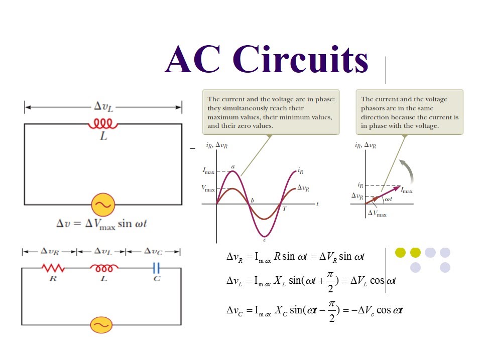
Phasor diagrams are graphical representations used to analyze and visualize the characteristics of alternating current (AC) circuits.The voltage is the same value across each parallel . Electronics is a branch of physics, electrical engineering, and technology concerned with the design and use of electrical circuits containing active electrical components (diodes, transistors, and integrated circuits) and passive electrical components (resistors, inductors, and capacitors) and connections . You now apply the phasor solution method to a simple linear circuit. as shown in the key to the right. Using Euler’s formula, the rectangular form of the phasor is. Microgrid applications––islanding or deciding where to detach . And at the end, voltage and current relationship between the basic circuit ele. After completing this chapter, you should be able to: Identify series-only and parallel-only sub-groups in series-parallel RLC networks. In an AC circuit with an inductor, the voltage across an inductor “leads” the current because of the Lenz’ law. In Figure 1, the mutual flux is indicated by the solid lines passing through the middle of the rotor, . Now, let us derive expressions of different electrical quantities. The combination of a resistor and inductor connected in parallel to an AC source, as illustrated in Figure 1, is called a parallel RL circuit.From the phasor diagram, it is clear that in an LR series circuit, the current always lags the voltage by an angle ϕ.E b = V – I a R a – jI a X s —–> (3). Analyzing voltages and currents in . RC Series Circuit Diagram. The conditions that exist in RC parallel circuits and the methods used for solving them are quite similar to those used for RL parallel circuits.

of EECS, The University of Michigan, Ann Arbor, MI 48109-2122. Take the current I (r. Now let’s dive into the topic and first of all, let’s get introduced to an actual transformer. We can therefore use .28 kHz = 1000 rad/sec, and the output is the voltage across . And how phasor and sinusoidal relate to each other. Impedance of RL Series Circuit: In an RL series circuit, there are only two circuit elements: a resistor and an .Learning Objectives. Version 1b, 21 September 2011 This paper gives an introduction to phasors and AC small-signal analysis with an emphasis on demonstrating how one can quickly understand the behavior of simple AC circuits without detailed calculations by examining the circuit and using high level rea-soning. In the given diagram, a RC series circuit is given with V=12V, C=8 \mu μ and R=800 k\Omega kΩ.

Video ansehen11:13Phasor diagram (& its applications) Phasors are rotating vectors having the length equal to the peak value of oscillations, and the angular speed equal to the angular frequency . Calculate the impedance and the phase angle theta (θ) of the circuit. The projection of the phasor onto an axis at a specific time gives the value of the quantity at that time. A 3-phase cylindrical rotor synchronous motor may operate at different power factors i.The phasor, F=A∠θ (a complex vector), as a thick blue arrow.Steps to draw a Phasor Diagram.
Phasor diagram (& its applications) (video)
Phasor Algebra in AC circuit Analysis: Addition and Multiplication
The circuit in Figure 3(a) is a practical parallel LC circuit, and the phasor diagram in Figure 3(b) represents the circuit conditions at resonance.Figure 3 RL Series circuit Impedance triangle.
Phasor Diagrams
The impedance phasor diagram may now be drawn to show the relationship between the values of resistance, reactance, and impedance in the circuit as shown in Figure 7.This circuit is a simplified model of a 60 Hz, 230-kV three-phase power system where only one phase is represented. The element impedances are
Circuit Theory/Phasor Analysis
This guide covers Series RLC Circuit Analysis, Phasor Diagram, Impedance Triangle, Solved Examples and several Review Questions Answers.Phasor-domain circuit analysis allows us to make this simplification by assuming sinusoidal steady-state excitation and replacing the time derivatives with complex numbers., as a complex number consisting of a real part and an imaginary part (in the context of circuit analysis, the imaginary portion of a complex number is preceded by the letter j instead of i).Equivalent circuit of a transformer is a schematic representation of a practical transformer that shows all electrical parameters such as winding resistance, reactance, admittance, susceptance, primary and secondary voltages, currents etc.The phasor diagram allows us to visualize the relationship between voltage and current in an AC circuit.s value) as a reference vector; Voltage drop in resistance VR = IR is taken in phase with the current vector; Voltage drop in capacitive reactance VC = IXC is drawn 90 degrees behind the current vector, as . Event Detection and Classification. It is seen that the presence of the resistive component in the inductive branch makes the I L phase angle (ɸ) slightly less than 90°. Three-phase AC is the dominant mode of electric power generation and distribution in modern societies.Explore math with our beautiful, free online graphing calculator.Phasor diagrams are a representation of an oscillating quantity as a vector rotating in phase space with an angular velocity equal to the angular frequency of the original trigonometric function .Z = √R2 + (XL − XC)2, which is the impedance of an RLC series AC circuit. V = VA cos ϕ + jVA sin ϕ.Series RLC Circuit.Suppose the above stationary vector in the polar form. With the network function, however, it becomes a simple matter of multiplying the input phasor with the network function, to get .
Phasor Diagram
A phasor measurement unit (PMU) .
Series RLC Circuit
Figure 4 Phasor diagram for the circuit of Figure 1.
RC Circuit
Parallel RL Circuit. The magnitude and phase of each wave can then be drawn as a vector, and the .2: This graph shows the relationships of the voltages in an RLC circuit to the current.
Phasor Introduction and Demo
Phasor Diagram for a Parallel RLC Circuit .Fig 4: Phasor diagram for an AC circuit with a capacitor.87° corresponds to the complex number 4 + j3.
Phasor diagram (& its applications)
Derivation of the Equivalent Circuit of Three-Phase Induction Motor. To describe a phasor, you need only the amplitude and phase shift (not the radian frequency).14b as if it were a “DC” circuit.
2a, can be transformed into a circuit in the stationary time frame, as shown in Fig.
- Phasenübergänge In Der Chemie – Latentwärmespeicher
- Pfotenkrankheiten Hund Bilder , Erkrankungen der Haut
- Photoshop Schnellauswahlwerkzeug
- Phosphorsäure Citronensäure Lösung
- Phpmyadmin Sql Dump | Remove DEFINER clause from MySQL Dumps
- Philipp Lahm Flick : DFB-Team: Lahm nimmt Flick und Völler in die Pflicht
- Pflichten Des Radfahrers Beim Überholen
- Philippines Cities , The Structure and Evolution of City System in the Philippines
- Photovoltaik Leistungsoptimierer
- Pforzheim Hochschule , Hochschule Pforzheim
- Phil Heath Workouts , Phil Heath’s Basic Back Workout Routine