Esp32 S3 Gpio – ESP32-S2, S3: inherent GPIO speed limit? #6657
Di: Samuel
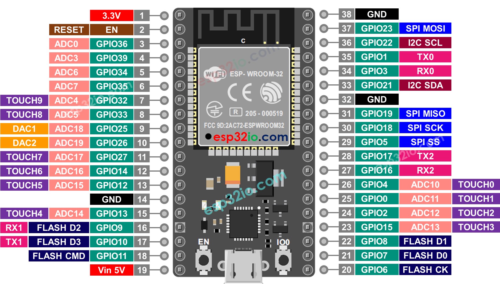
In newer chips (e. This way I can use JTAG via USB and get the MTCK floating. ESP32 verfügt im Vergleich zu Arduino UNO- oder ESP8266-Boards über eine größere Anzahl von Pins. Postby ESP_Angus » Thu Jan 05, 2017 10:43 pm.Espressif ESP32 Official Forum.GPIO The pins of ESP32-S3 can be configured via IO MUX or GPIO matrix. Pinout ESP32 NodeMCU Module. There is an internal touch channel that is not connected to any external GPIO. There are some GPIOs with special restrictions . It has 45 programmable GPIOs and supports a rich set of peripherals. Among different chips, the Vref varies, the median is 1.In the off chance you are using gpio_get_level (40), that function will always return 0 if the gpio is set to output.
Inter-Integrated Circuit (I2C)
SPI slave device.4 GHz Wi-Fi (802.Otherwise the GPIO and signal will be connected via the GPIO Matrix. If necessary, you can consider connecting the positive and negative terminals of . The Arduino Nano ESP32 is a Nano form factor board based on an ESP32-S3 SoC.3V, when it is released, the input remains at 2.py set_flash_voltage command permanently sets the internal flash voltage regulator to either 1.Setting up a channel of the LEDC is done in three steps.
LED Control (LEDC)
ESP32-S3 is a dual-core XTensa LX7 MCU, capable of running at 240 MHz.
Hi, I am not able to configure the pin IO42 on my ESP32-S3 (ESPRE-S3-DevKitC-1 v1. But I can not burn this fuse, it is not even in the summary.oldcurmudgeon December 9, 2023, 10:20pm 4.
Die ESP32-Evolution: S2, S3, C3
The ESP32-S3 chip features 45 physical GPIO pads. So they can detect variations induced when touching the GPIO’s with a finger.original ESP32 could handle this, but peripherals in the new devices are different.
How to use GPIO19 and GPIO20 in esp32-S3
The ESP32-S3 ADCs can measure analog voltages from 0 V to Vref. As long as each Device is accessed by only one task, the driver is thread-safe.ESP32-S3 GPIO20 remove startup glitch. The ESP32 chip has the following strapping configuration pins: GPIO 0; GPIO 45; GPIO 46; These pins . However, if multiple tasks try to access the same SPI Device, the driver is not thread-safe. Bluetooth 5, BLE + Mesh. It means that in the scenario of the XYZ . ESP32 S3) befindet sich heute im Programm.11 b/g/n Wi-Fi and Bluetooth 5 (LE) connectivity that provides long-range support.Re: ESP32-S3 enabling GPIO39-GPIO42. I configured the GPIO20 (USB D+) as a normal output pin in SETUP, but during chip boot cycle it gets pulled high for about 170ms.4GHz Wifi – 802. Timer Configuration by specifying the PWM signal’s frequency and duty cycle resolution.
Schematic Checklist
out_w1ts = ((uint32_t)1 << IO_PIN_Number); to set .IO MUX and GPIO Matrix (ESP32-S3 technical reference manual) Wi-Fi® The Nano ESP32 has a NORA-W106 module which has the ESP32-S3 SoC embedded. On the board supporting the ESP32 module, it has diagnostic LEDs connected to a few GPIOs and driven by a small MOSFET each.On the ESP32-S3, this will require using a GPIO to act as a voltage sensing pin to detect when VBUS goes above/below the prescribed thresholds. Form the docs I understand that I need to burn EFUSE_DIS_PAD_JTAG = 1. There are some guides from people who tested the pins for such behavior such as this one: The problem is that with . Postby yohnsee » Tue Oct 24, 2023 12:32 pm. The following table shows the default ESP32-S3 WT32-SC01 Plus configuration, which is sorted according to the defined functionality of the GPIOs. A single I2C controller can be a master or a slave.
ESP32-S3-Pico
Note that unlike ESP32, ESP32-S3 only supports configuring channels in low speed mode. This module supports Wi-Fi® communication over the 2.Bei einem GPIO- oder Timer-Wake-up (nur ein Pin als Wake-up definierbar) aus dem Deep Sleep, bootet die MCU (ESP32, S2, S3, C3) komplett durch. GPIO stands to General Purpose Input Output, and is responsible to control or read the state of a specific pin in the digital world. USB back-feed protection.This is very convenient if you want to port a project from another Nano board, as you can preserve the same wiring and pin numbers in the code. Right now, I am using two LEDs (one .
Arduino Nano ESP32 Cheat Sheet
ESP32-S2, S3: inherent GPIO speed limit? #6657
There are several examples provided bundled with the Board Package that showcase how to make HTTP requests, host web .1! Leaf S3! Lilygo T-SIM A7670x! Lilygo T7 Mini32 v1. We have tested .
ESP32
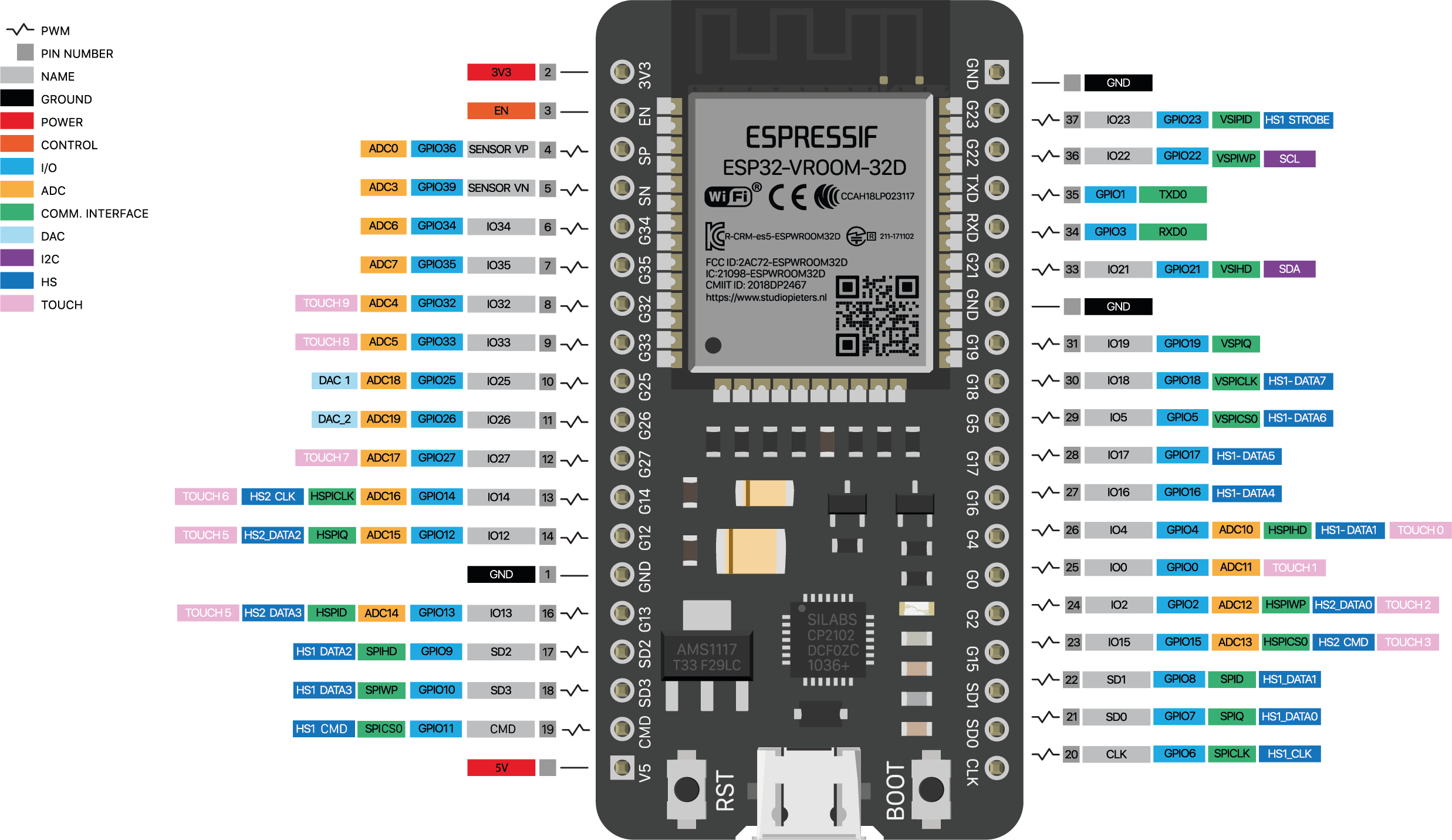
Select an esp32s3 as your board type. Essentially, this capability means that we can route the internal peripheral into a different physical pin using the IO MUX and the GPIO Matrix. The ESP32 architecture includes the capability of configuring some peripherals to any of the GPIOs pins, managed by the IO MUX GPIO . ESP32-S3 supports both I2C Standard-mode (Sm) and Fast-mode (Fm) which can go up to 100KHz and 400KHz respectively.The ESP32-S3 has up to 45 GPIO pins that can be assigned to different functions through programming.
ESP32-S3 Hardware Pinout and Details
GPIO performance on ESP32-S2 and S3 seems to be sub-par, with even a tight bit-toggling loop going direct to GPIO registers only managing 8 MHz.ESP32-S3-WROOM-2 EN GPIOs Antenna OSPI Flash SPICS0SPICLKSPIDSPIQ co h OSPI Flash SPICS0SPICLKSPIDSPIQ co h OSPI PSRAM SPIIO4 OSPI PSRAM SPIIO5SPIIO6SPIIO7SPIDQS SPIIO4SPIIO5SPIIO6SPIIO7SPIDQS Figure 1: ESP32-S3-WROOM-2 Block Diagram EspressifSystems 9 SubmitDocumentationFeedback ESP32 .9V recommended max may be a mistake in the ESP-WROOM32 datasheet, the ESP32 datasheet suggests you can’t go this high.All of our ESP32-S3 boards include the following features: Dual 32bit Xtensa LX7 cores running up to 240Mhz. Native USB + USB Serial JTAG + USB OTG. However, ESP32-S3 pins are 3. Most of these digital GPIO pins can be configured with internal pull-up or pull-down resistors. An SPI bus may be connected to one or more Devices. In order to convert voltages larger than Vref, input voltages can be attenuated before being input to the ADCs. How do yo do the following on the S3 higher than 31 ? //This can only be used when the IO_PIN_Number is 0-31 //Use GPIO.Re: Control the onboard LED on the ESP32-S3 – ESP32-S3-DevKitC-1 Post by blanchehermine » Wed Mar 29, 2023 5:33 am There’s an example in the esp-idf-v5. Um mit ESP32 zu arbeiten, ist eine ausreichende Kenntnis seines Pins .gpio & rtc gpio . 4 Löchern zum Befestigen an jeder Ecke. Board Configuration.
When the button is pressed, the input to GPIO0 = 3. pinMode(GPIO_pin, OUTPUT); Then you can drive the pin HIGH or LOW to change the digital state of that pin. If you want to connect a switch button to enter the boot mode, this has to be a strong pull-down. For more details, see ESP32-S3 Technical Reference Manual > IO MUX and GPIO Matrix (GPIO, IO_MUX) [ PDF ]. Jeder dieser Pins ist für bestimmte Funktionen ausgelegt. Strapping Pins on the ESP32-S3.ESP32 S3 Wroom-1! Esp32 S2 Mini V1. Using gpio_set_level() is just to slow.Since all GPIO pins of the XIAO ESP32S3 are assigned their own functions, we do not have a GPIO configured for the battery pin.5! Lolin D32! Freenove ESP32-S3! Freenove ESP32-Wroom! Nano ESP32! Sailor Hat ESP32! StickLite-V3-ESP32S3! T-Display S3 AMOLED! TinyPICO Nano! TinyPico V3! TTGO Display . Ein echter Deep Sleep ist das also nicht.
ESP32-S3 gpio
GPIO Matrix and Pin Mux.Designed for AIoT applications. For example, this peripheral is widely used to create the LED blinking or to read a simple button. This means a GPIO can be high or low at reset without changing the flash voltage. Development Environment Configuration.
You can turn the LED ON by writing a HIGH or 1, they’re the same thing.
ESP32-S3
6) as a normal GPIO output, with the following code:1\examples\get-started\blink folder, which has a functionFirst of all, you need to define the GPIO pin to operate in output mode in the setup () function, using pinMode () Arduino function as shown below. For example a 10k resistor to GND. srnet December 10, 2023, 8:01am 5. I have examined the board and directly probed the pins on the ESP32-S3-WROOM1 – the pins are working as usual.11 b/g/n) and Bluetooth®5 (LE) Built around ESP32-S3 series of SoCs, Xtensa®dual-core 32-bit LX7 microprocessor Flash up to 8 MB, optional 2 MB PSRAM in chip package 39 GPIOs, rich set of peripherals On-board PCB antenna or external .I need to toggle a GPIO pin as fast as I can. For slow 5V signals, it should be possible (though hacky) to use a single high value series resistor .
ESP32-S3 引脚参考大全
A particular situation requires 16-24 MHz. Thus, in order to detect the . Thus, even if VBUS rises/falls above/below the thresholds mentioned above, it would still appear as a logic HIGH to the ESP32-S3. Die Geschichte des ESP32 ist eine von Innovation und kontinuierlicher Verbesserung. 8MB of extra QSPI PSRAM. It is recommended to develop with the VSC plug-in.This guide explains how to select the boot mode correctly and describes the boot log messages of ESP32-S3. Der ESP32 brachte wichtige Neuerungen wie . Die Maße vom ESP32 betragen 48mm x 26mm incl. Insgesamt verfügt er über 38 Pins.For detailed information about the ESP32-S3 SoC variant (family) and ESP32x SoCs, see section ESP32 SoC Series. The ESP32-S3 has a 45k ohm internal pull-up/pull-down resistor at GPIO0 (and other pins). Postby Jonathan2892 » Thu Nov 03, 2022 2:00 pm. I ran across the following, and wanted to try it but the GPIO pin I want to use is 46.The SPI Master driver allows multiple Devices to be connected on a same SPI bus (sharing a single ESP32-S3 SPI peripheral). RISC-V Ultra Low Power Co-processor.
How to set GPIO42 on ESP32-S3 as normal GPIO output?
IO MUX provides the default pin configurations, whereas the GPIO matrix is used to route signals from peripherals to GPIO pins.Re: 5V tolerance.
GPIO & RTC GPIO
ESP32-S3 has 2 I2C controller (also called port), responsible for handling communication on the I2C bus. Dear forum, I designed a custom PCB board for the ESP32 S3 Wroom-1U module, and found an annoying behavior during testing. For more information about IO MUX and GPIO matrix, please refer to ESP32-S3 Technical Reference Manual > Chapter IO MUX and GPIO .

Go to Files->Examples->ESP32->GPIO->BlinkRGB for an example of how to use the onboard RGB LED.
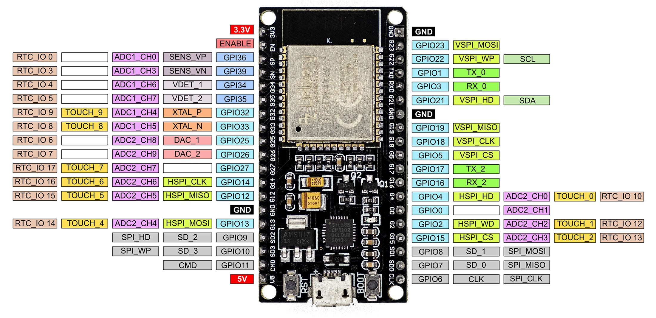
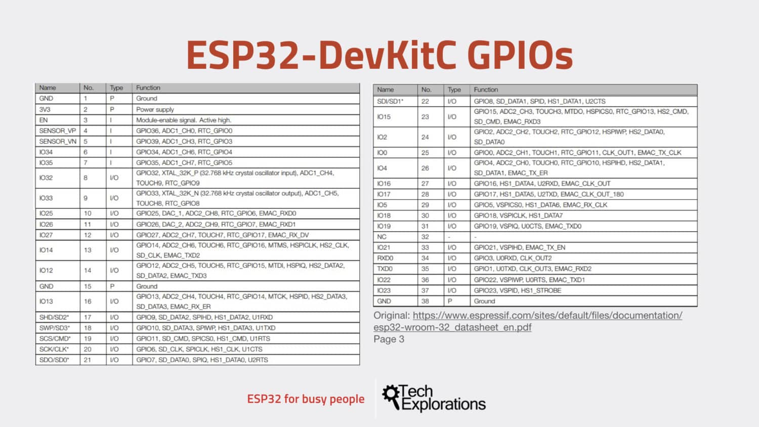
Each pad can be used as a general purpose I/O or can be connected to an internal peripheral .The GPIO is commonly used to write and read the pin state.We are using a ESP32-S3-DEVKITC-1-N8 for a POC.esp32-s3 提供了多达 14 个电容式传感 gpio,能够探测由手指或其他物品直接接触或接近而产生的电容差异。 这种设计具有低噪声和高灵敏度的特点,可以用于支持使用相对较小的触摸板。设计中也可以使用触摸板阵列 以探测更大区域或更多点。esp32-s3 的触摸传感器同时还支持防水和数字滤波等功能来 . Some GPIO pads cannot be used or do not have the corresponding pin on the chip package. esp32-s3 芯片具有 45 个物理 gpio 管脚(gpio0 ~ gpio21 和 gpio26 ~ gpio48)。每个管脚都可用作一个通用 io,或连接一个内部外设信号。通过 gpio 交换矩阵、io mux 和 rtc io mux,可配置外设模块的输入信号来源于任何的 gpio 管脚,并且外设模块的输出 . For ESP32-S2 there are two methods to operate dedicated GPIO: by accessing registers and by using specialized CPU instructions.ESP32 ist ein Mikrocontroller-Board, das eine Reihe von GPIO-Pins für verschiedene Zwecke hat.
ESP32-S3: GPIO0 pull-down Issue
The short answer is that dedicated GPIO feature is supported for ESP32-S3.The ESP32-S3’s touch functionality provide two sets of APIs for doing this. Apart from its 512 KB of internal SRAM, it also comes with integrated 2.Note: SPI, I2C, UART, and other interfaces can be mapped to most GPIOs through the GPIO Matrix and IO MUX, see the ESP32-S3 datasheet for details. 300 ms und man muss mühsam seinen Programmstatus aus dem RTC-Speicher rekonstruieren. Hey, I need GPIO39 (MTCK) floating after reset. Typically, an I2C slave device has a 7-bit address or 10-bit address. The measurements from this denoise pad can be used to filters out interference introduced on all channels, such as noise introduced by the power supply and external EMI.The SPI controller peripheral inside ESP32-S3 that initiates SPI transmissions over the bus, and acts as an SPI Master. Positional arguments: voltage – . If you use LED_BUILTIN as the LED name, the RGB LED will blink white like a normal LED. We have a 100kΩ pull down resistor on GPIO0.
ESP32-S3 enabling GPIO39-GPIO42
Auch die WLAN- und sicherheitsorientierte Variante der S Reihe (z.Hi @nopnop2002, thanks for the assistance. Each Device shares the MOSI, MISO and SCLK signals but is only active on the bus when the Host asserts the Device’s individual CS line. Entwickelt von Espressif Systems, folgte der ESP32 auf seinen beliebten Vorgänger, den ESP8266, mit dem Ziel, noch mehr Funktionalität und Flexibilität zu bieten.Die ESP32 Familie – Eine Erfolgsgeschichte. This board is part of the Arduino Nano Family, and follows the same pinout as all Nano boards. There are 4 available attenuation options, the higher the attenuation is, the higher the measurable input .I was trying to use the GPIO19 and GPIO20 in esp32-S3 but these pins always stay High, I tried disabling the TinyUSB driver in the esp-idf menuconfig but still, I was not able to use those pins as generic GPIOs. These can sense variations in anything that holds an electrical charge, like the human skin.0! ESP32 POE! ESP32 C3 Mini! ESP32 C3 Zero! ESP32 Pico Kit v4. this means that we cannot get the battery voltage at the software level by reading the analog value of one of the GPIOs. Otherwise, from what I can see, Arduino’s pinMode () makes a call to gpio_config (), which does a few more things than gpio_set_direction (), notably first resetting the pin and configuring the iomux. ULTRA LOW Deep Sleep Current. Channel Configuration by associating it with the timer and GPIO to output the PWM signal. ESP32-S3 or ESP32-C3) the first method has been been removed and there are no dedicated GPIO registers . These pins can be easily integrated into capacitive pads and replace mechanical buttons. Back to table of contents.The ESP32-S3 has 14 internal capacitive touch sensors.
ESP32-S3: Dedicated GPIO
We power the device by pressing a button, which is also connected to GPIO0 to determine when it is pressed again.ESP32-S3-MINI-1 ESP32-S3-MINI-1U.I have a very simple sketch being uploaded to an ESP32-S3, like this: void setup() { pinMode(GPIO_NUM_20, OUTPUT); pinMode(GPIO_NUM_21, OUTPUT); } void loop() { delay(500); } These two GPIO pins are connected to the input side of two typical MOSFET relays controlling much larger outputs. Small-sized module supporting 2.With previous versions of the ESP32, there have always been some GPIO pins which may briefly emit a PWM signal at boot or a logic HIGH, causing some undesirable activity in whatever the pins are connected to.
SPI Master Driver
The following development system is Windows by default. For example, if on an ESP32 the call uart_set_pin(0, 1, 3,-1,-1) is performed, as GPIO1 is UART0’s default TX pin and GPIO3 is UART0’s default RX pin, both will be connected to respectively U0TXD and U0RXD through the IOMUX, totally bypassing the GPIO matrix. I’ll check up on this.
ESP32 GPIO (Digital Inputs & Digital Outputs)
GPIO: Das ESP32 NodeMCU Module verfügt über 38 GPIO .
- Erwerbslebensförderung Nrw – Beratung — Weiterbildungsberatung NRW
- Escape Raum Marburg _ Virtuelle Realität
- Estee Lauder Holiday Collection
- Erzeugerpreisindex Für Gips , Erzeugerpreise Mai 2023: +1,0 % gegenüber Mai 2022
- Erzengel Gabriel Maria Gern – Verkündigung des Herrn
- Essen In Nürnberg Tipps | Nürnberg Insidertipps
- Erwartungshorizont 50 Maßnahmen
- Ethanol Herstellung Einfach Erklärt
- Esc Auftritte Früher : ESC 2015: Früher war mehr Show
- Essbare Sukkulenten _ 1a-Saatgut
- Eskimos In Deutschland : Eskimo rassistisch? Was ist an dem Wort falsch? Ist Inuit besser?
- Erythrozytose Blutbild : Erythropoetin (EPO) als Laborwert
- Erzählerische Mittel Stellung | Erzähltechnik
- Essigreiniger Test | Der beste Badreiniger
- Esprit Store Ratingen _ Esprit